Chapter 1: System Components
Architecture, component inventory, working principles, and operational flows
1.1 System Architecture
The log security system is deployed across three distinct security zones, each with its own trust boundary, network policy, and component set. This multi-zone architecture is the foundational security control that prevents a compromise in one zone from directly affecting the evidence integrity in another. The three zones — Production, Security Operations, and Audit & Compliance — communicate only through explicitly defined, firewall-enforced channels with minimal required permissions.
The Production Zone hosts the log sources and zone collector pairs. Each zone maintains at least two collectors in an active-active or active-standby configuration to eliminate single points of failure. Collectors in the Production Zone have no inbound connections from the central platform; they only make outbound connections to the Ingest Gateway cluster in the Security Operations Zone. This asymmetric trust model ensures that a compromise of the central platform cannot be used to tamper with source-side collection.
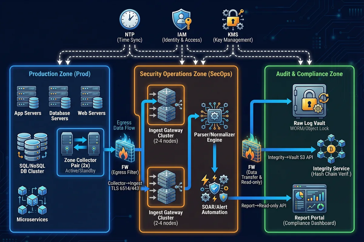
The Audit & Compliance Zone is the most restricted zone in the architecture. It contains the Raw Log Vault with WORM/Object Lock enforcement, the Integrity Service, and the Report Portal. Access to this zone is strictly read-only for most roles, with write access limited to the Ingest Gateway's raw-write pipeline and the Integrity Service's manifest writes. Administrative access requires dual control and is fully logged to the immutable Admin Audit Store.
Core Boundary: Log sources, collectors, secure transport, central ingest, raw vault, index/search, integrity verification, and access governance. Optional Boundary: SOAR automation, UEBA, long-term archive tier, and offline escrow for maximum assurance environments.
1.2 Components and Functions
The system comprises thirteen distinct components, each with a well-defined responsibility, input/output interface, and key performance indicator. The component inventory map below shows the layered relationship between components and the data formats that flow between them. Understanding these interfaces is critical for capacity planning, failure mode analysis, and acceptance testing.
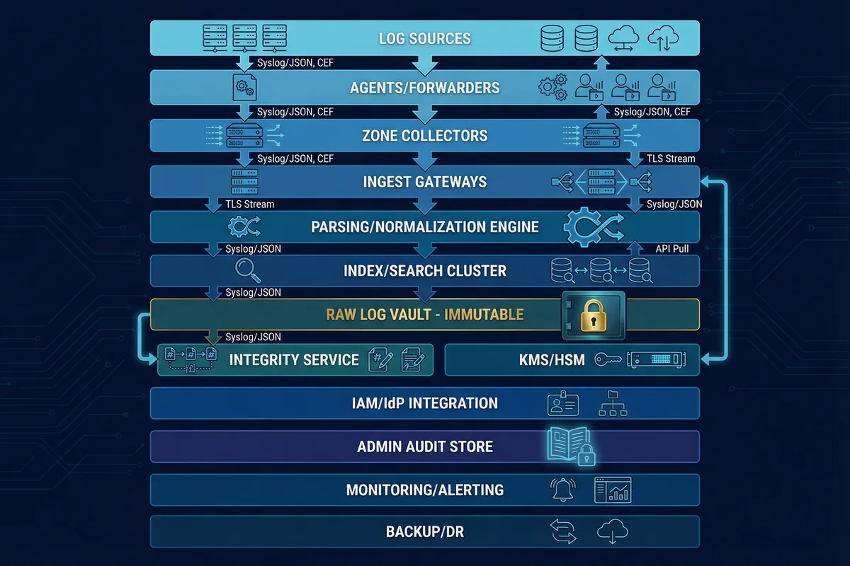
| Component | Responsibility | Inputs | Outputs | Key KPIs | Mismatch Risk |
|---|---|---|---|---|---|
| Log Sources | Generate audit records; enforce audit policy | App/OS events | Syslog/Files/API | Coverage %, event completeness | Missing critical fields; disabled audit categories |
| Agent/Forwarder | Collect local logs; buffer; sign/label | Files/ETW/Journal | TLS stream | Buffer depth, drop rate | Buffer too small → loss; parsing errors |
| Zone Collector Pair | Aggregate; enforce allowlist; retry | Agent streams/syslog | mTLS stream | EPS capacity, queue latency | Single collector → SPOF; mis-sized disk |
| Ingest Gateway Cluster | Terminate TLS; rate-limit; route | mTLS input | Queue/topic | Handshake success %, throttle events | No throttling → collapse under burst |
| Parsing/Normalization | Normalize fields; enrich context | Raw events | Normalized schema | Parse success %, schema drift | Incorrect mapping → analyst misinterpretation |
| Index/Search Cluster | Searchable hot data | Normalized events | Queries/results | Query latency, shard health | Index tampering/accidental delete |
| Raw Log Vault (Immutable) | Preserve evidence in WORM | Raw segments | Read-only retrieval | Immutability lock success, durability | If not immutable → silent changes possible |
| Integrity Service | Hash chain/sign; verify; report | Raw segments | Manifests/reports | Verification coverage %, failure rate | No periodic verification → undetected tamper |
| KMS/HSM | Protect keys; rotation | Key requests | Keys/unwrap | Rotation compliance, access logs | Key sprawl; no separation of duties |
| IAM/IdP + RBAC | Authentication/authorization | Identities | Tokens/roles | MFA compliance, privileged session audit | Over-privilege, shared accounts |
| Admin Audit Store | Record privileged actions | Admin logs | Immutable audit trail | Completeness, non-repudiation | Admin can delete their own traces |
1.3 Working Principles
Startup Sequence
The system startup sequence is designed to establish trust before accepting any log data. Each component must verify its own integrity and establish authenticated connections before entering operational mode. This prevents a partially-initialized system from accepting logs without the full security controls in place.
OS Hardening Verification
Collectors boot and verify OS hardening baseline, mount local buffer storage, and load device identity certificate (TPM-backed where available).
Time Synchronization
Time sync establishes to authenticated NTP. Collector refuses "trusted mode" if time drift exceeds the configured threshold, preventing log ingestion with untrusted timestamps.
mTLS Connection Establishment
mTLS connection established to ingest gateway. Allowlist and certificate CN/SAN verified. Connection rejected if certificate is not in the trusted allowlist.
Initial Health Check
Collector reports health metrics to monitoring platform. Buffer disk capacity, queue depth, and NTP drift status are all verified before entering full operational mode.
Normal Operation Flow
During normal operation, the system follows a strict write-ahead-to-raw-vault policy. Raw evidence is written to the immutable vault before or alongside indexing, ensuring that even if the indexing pipeline fails, the raw evidence is preserved. The integrity service maintains a continuous hash chain across all stored segments.
Source → Forwarder → Collector
Sources produce logs → forwarder buffers locally → collector aggregates and tags metadata (zone, device ID, receive time).
Collector → Ingest (Segmented Batches)
Collector batches events into segments (5–60 seconds or size-based) and transmits over mTLS to the ingest gateway cluster.
Ingest → Raw Vault (Write-Ahead)
Central platform writes raw segment to immutable vault first, then parses to normalized schema and indexes into hot search. Raw evidence is never dependent on indexing success.
Integrity Service → Hash Chain → Manifest
Integrity service maintains hash chain per source/stream/segment and signs manifests. Periodic verification jobs re-check vault data against stored manifests.
Exception and Recovery Flows
The system is designed to handle four primary exception scenarios without evidence loss. Each exception has a defined behavior, recovery procedure, and acceptance test to verify correct handling.
Exception 1: Network Outage Between Zone Collector and Ingest
Behavior: Collector switches to store-and-forward, queues locally, applies backpressure to agents, and drops only after buffer is full (with explicit alarms). Recovery: On reconnect, collector replays in order; ingest de-duplicates using segment IDs.
Exception 2: Clock Drift or NTP Compromise
Behavior: Collector monitors drift; if drift exceeds threshold, marks logs "time_untrusted" and triggers alert; optionally isolates from ingest until time is restored. Recovery: Resync time, record correction event, keep both event_time and receive_time for forensic tracing.
Exception 3: Attempted Tamper at Central Index
Behavior: Index deletion or reindex triggers admin audit trail; raw vault remains immutable. Integrity verification still passes only for original raw; any mismatch is flagged immediately. Recovery: Rebuild index from raw; produce incident report with who/when/what.
Exception 4: Collector Disk Nearing Full
Behavior: Alert at 70/85/95% thresholds; apply throttling; preserve highest priority logs per policy. Recovery: Expand disk, add collector, reduce noise, or reroute to alternate path.